Configuring advanced channel settings (Input)
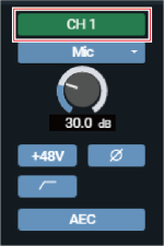
Setting channel names and colors
Set names and colors for each channel.
-
Click on the channel name.
-
Click on the text box and enter a channel name.
-
Select a color.
-
Click “OK”.
The channel name and color are set.
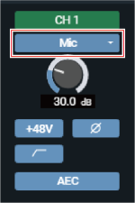
Changing the input type
Specify the input type.
-
Click the area in the red box on the screen.
-
Select the input type from the pull-down menu.
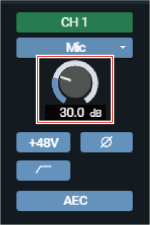
Adjusting the gain
Adjust the input gain of the audio input.
-
Adjust the gain by dragging (vertical direction) the meter.
- Because the level meter will turn blue and display the pre-fader level when the gain is adjusted, adjust while monitoring that level.
|
|
|
|---|
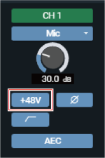
Turning the phantom power ON/OFF
Turn ON/OFF the phantom power (+48V). This setting can be made only when “Mic” is selected as the input type.
-
Click the area in the red box on the screen.
- With each click, the setting switches between ON (blue) and OFF (no color).
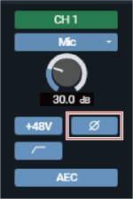
Turning the phase ON/OFF
Invert the input audio phase.
-
Click the area in the red box on the screen.
- With each click, the setting switches between ON (blue) and OFF (no color).
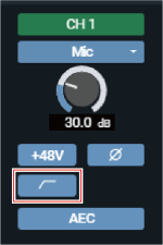
Turning the low-cut ON/OFF
Specify whether or not to remove low frequencies from the audio signal.
-
Click the area in the red box on the screen.
- With each click, the setting switches between ON (blue) and OFF (no color).
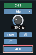
Turning the AEC ON/OFF
Turn the AEC (Acoustic Echo Canceler) ON/OFF.
-
Click the area in the red box on the screen.
- With each click, the setting switches between ON (blue) and OFF (no color).
Checking SmartMixer status
-
Check the area in the red box on the screen.

Display Status 
Turned OFF. 
Turned ON. 
Turned ON, and SmartMixer active. The set group color will be displayed.
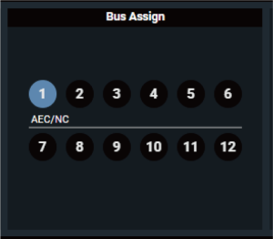
Checking the bus assignment
-
Displays the assigned bus for each channel.
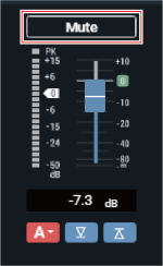
Turning the mute ON/OFF
Switch the mute setting between ON and OFF for each channel.
-
Click the area in the red box on the screen.
- Mute turns ON (red)/OFF (no color) each time the switch is clicked.
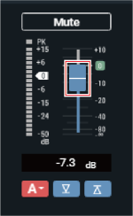
Adjusting the input level
Adjust the audio input level for the channel.
-
Drag the volume adjustment dial, and move it up and down to adjust the input level.
Display Status 
If the channel faders are set to the same group on this screen on the primary and extension devices, and the faders are assigned under “Operator Page” > “Fader Settings” on the primary device, the fader assigned for the primary device will be used for controlling the levels of all channels in the same group. 
Set the lower limit of the audio input level. The volume position when the setting is turned ON (blue) will be set. 
Set the upper limit of the audio input level. The volume position when the setting is turned ON (blue) will be set.
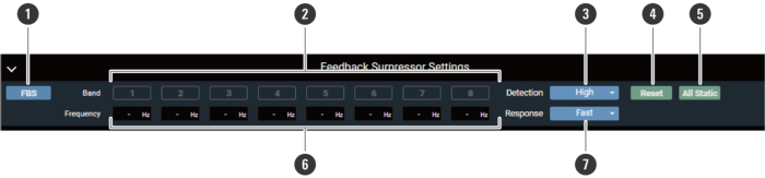
Setting the FBS (feedback suppressor)
-
FBS ON/OFF
Switch the FBS ON (blue)/OFF (no color).
-
Band
Displays the status of each band. You can also switch between dynamic and static.
Display Status 
Dynamic state.
Indicates that the feedback frequency is detected, and the FBS is functioning. The feedback frequency remains for 15 seconds and is then automatically cleared. Until a new frequency is detected, the feedback frequency display is left blank and turns into a standby state.
Static state.
Click this icon in a dynamic state to lock the band and enter a static state. Click the icon again to cancel a static state of the band and enter a standby state.
Standby state.
Waiting for a new feedback frequency to be detected. -
Detection
Select the strength to suppress the feedback.
-
Reset
Click to reset the detected frequencies. Once reset, new frequencies are detected (but those of the bands in a static state are not reset).
-
All Static
Set all bands to the static state.
-
Frequency
Displays the frequencies of the detected feedbacks.
-
Response
Select the speed of suppressing the feedback.
|
|
|
|---|
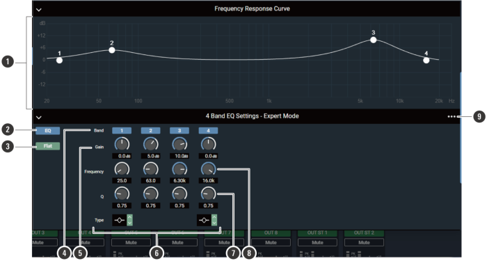
Setting the 4-band EQ
-
Frequency Response Curve
Display and edit the EQ frequency response waveform. The pointer for each band indicates the frequency and the gain position. Edit the frequency and the gain by dragging a pointer.
-
EQ ON/OFF
Switch the EQ ON (blue)/OFF (no color).
-
Flat
In all bands, change the gain to 0 without changing the current frequency.
-
Band
Display and switch the ON (blue)/OFF (no color) setting of each band.
-
Gain
Adjust the gain of each band.
-
Type
Change the filter type (applicable to bands 1 and 4 only).
-
Q
Adjust the Q value of each band.
-
Frequency
Adjust the frequency of each band.
-
Settings menu
Recall/save an EQ preset, reset the EQ frequency response waveform, or switch between easy and expert screen modes.
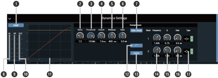
Configuring dynamics function settings
-
CMP ON/OFF
Switch the EQ ON (blue)/OFF (no color).
-
Ratio
Set the compressor ratio.
-
Threshold
Set the compressor threshold.
-
Attack
Set the compressor attack time.
-
Release
Set the compressor release time.
-
Gain
Set the Dynamics output gain.
-
Side Chain
Switch between compressor (no color) and DeEsser (blue) modes.
-
Dynamics IN
Indicates the level of audio input to Dynamics.
-
GR (Gain Reduction)
Indicates the level of audio gain suppression by the compressor.
-
Dynamics OUT
Indicates the level of audio output from Dynamics.
-
Dynamics graph
Indicates the Dynamics characteristic.
-
Low-cut ON/OFF
Turn the low-cut ON/OFF.
-
Listen
Turn the Listen function ON/OFF.
-
Frequency
Adjust the frequency of the DeEsser.
-
Q
Adjust the Q value of the DeEsser.
-
Gain
Adjust the gain of the DeEsser.
-
Type
Change the filter type.