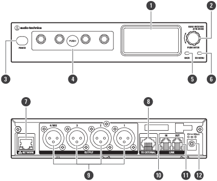
ATW-R1440
This receiver is a combination of a receiver chassis (ATW-RC14) and receiver unit (ATW-RU14).
-
Display
Displays the receiver state and settings menus.
-
Control dial
Turn the dial to select a setting item and press to confirm.
-
Power button
Turns the power on or off.
-
Receiver unit
You can remove this unit to install it externally.
-
BACK button
Press to take the display back one screen. Press and hold to return to the main screen.
-
CH MENU button
Press to display the channel settings menu. Each press of this button switches the channel to set.
-
NETWORK port
Connecting this port to a PC via Ethernet allows you to configure settings and monitor from the PC.
-
External receiver unit port
When externally installing the receiver unit, connect a LAN cable (Cat. 5e or higher) to this port.
-
AF balanced output connector (XLR 3-pin male)
-
LINK IN port
When linking multiple receivers, connect the included link cable to this port.
-
LINK OUT port
When linking multiple receivers, connect the included link cable to this port.
-
DC input jack
Connect the included AC adapter.
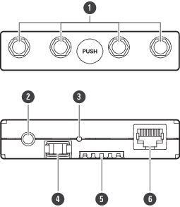
ATW-RU14
-
Antenna connector
Attach an included antenna.
-
Camera thread (1/4-inch)
Use this thread to secure the receiver unit when installing it externally.
-
Indicator lamp
Lights when the device is on. This lamp also shows the status of this receiver unit. Refer to Indicator lamps for details.
-
Latch module
This fixing module is used when the receiver unit is stored in the receiver chassis.
-
Internal connection terminal
-
External connection port
When externally installing the receiver unit, connect the LAN cable (Cat. 5e or higher) from the receiver chassis to this port.