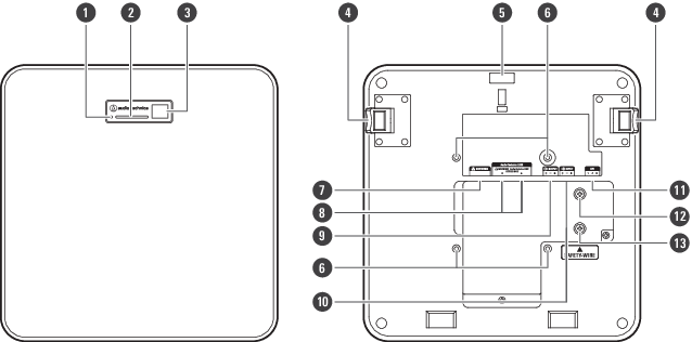
Microphone
ATND1061LK
-
Reset button
Insert the tip of a pin or other thin device and press this button to reset the microphone.
-
Indicator lamp
-
IR receiver
-
Release button
-
Hole for zip tie
-
Screw holes for VESA mount
Used when installing with a VESA mount.
-
Network port
Used to connect the LAN cable (CAT5e or higher). Connect to the local area network and perform external control using the application.
-
Audio-Technica LINK A/B ports
Used for Audio-Technica LINK. Used for connecting the LAN cable (CAT5e or higher). (Make sure to use conductor with a diameter of 24AWG or larger and a shield.)
-
Analog output port
Used to connect the balanced cable.
+: Hot
−: Cold
G: Ground -
Analog input port
Used to connect the balanced cable.
+: Hot
−: Cold
G: Ground -
GPI port
For details, see GPI port.
1: GPI1
2: GPI2
G: Ground -
Screw for grounding
Perform grounding as necessary.
-
Screw for seismic cable
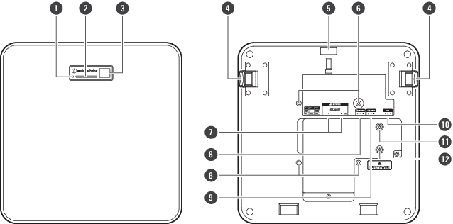
ATND1061DAN
-
Reset button
Insert the tip of a pin or other thin device and press this button to reset the microphone.
-
Indicator lamp
-
IR receiver
-
Release button
-
Hole for zip tie
-
Screw holes for VESA mount
Used when installing with a VESA mount.
-
Network A/B ports
Dante network ports. Used for connecting the LAN cable (CAT5e or higher). (Make sure to use conductor with a diameter of 24AWG or larger and a shield.) Connect to the local area network and perform external control using the application.
The power supply turns on when the network A port is connected to a PoE switching hub. -
Analog output port
Used to connect the balanced cable.
+: Hot
−: Cold
G: Ground -
Analog input port
Used to connect the balanced cable.
+: Hot
−: Cold
G: Ground -
GPI port
For details, see GPI port.
1: GPI1
2: GPI2
G: Ground -
Screw for grounding
Perform grounding as necessary.
-
Screw for seismic cable
Indicator lamp
The colors of the indicator lamp can be used to confirm the microphone status.
| Indicator lamp | Status |
|---|---|
| Lights in green [1] | Normal (unmuted) |
| Lights in red [1] | Muted |
| Lights in cyan [1] | Power Save Mode |
| Flashes in red (1 second intervals) | Connecting to the network |
| Flashes in red (2 second intervals) |
Error |
[1] The colors of indicator lamp can be changed in “LED Settings”.
|
|
|
|---|