Connection procedure
-
Connect the output terminals (RJ45 jacks) on the microphone cable to the included RJ45 breakout cables by using commercially available STP cables.
- Connect microphone output terminals A and B to RJ45 breakout cables A and B, respectively.
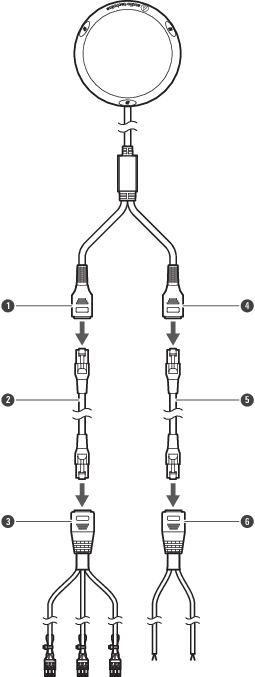
- Microphone output terminal A
- Commercially available STP cable (MIC 1 to MIC 3)
- RJ45 breakout cable A
- Microphone output terminal B
- Commercially available STP cable (LED control / CLOSURE control)
- RJ45 breakout cable B
-
Connect the output terminals on the RJ45 breakout cables to a device that has a microphone input (balanced input) that is compatible with a phantom power supply.
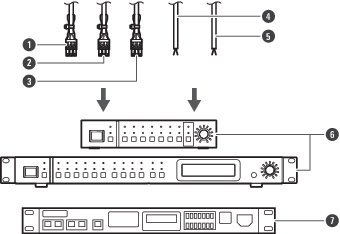
- MIC 1
- MIC 2
- MIC 3
- LED control
- CLOSURE control
- ATDM series DIGITAL SMARTMIXER™
- Third-party mixer
- The product requires 20 to 52 V DC phantom power supply for operation.
- The output connectors are Euroblock connectors with polarity as shown in the Wiring table.